
The processor will handle straight logs up to 13″ diameter. Anything larger needs to be broken down manually.
Typically this means a chainsaw and either the small splitter, or, if I’m feeling sporty, the maul.
Fine for small quantities, but I need something faster for large scale production.
This project began quite a few years ago with the intent to build a processor. Of course, I really didn’t know what I was doing, and finally decided to build a small splitter so as to learn more before gluing a large mass of steel together into something useless.
So I parked the bones at the edge of the hayfield and moved on to other things.
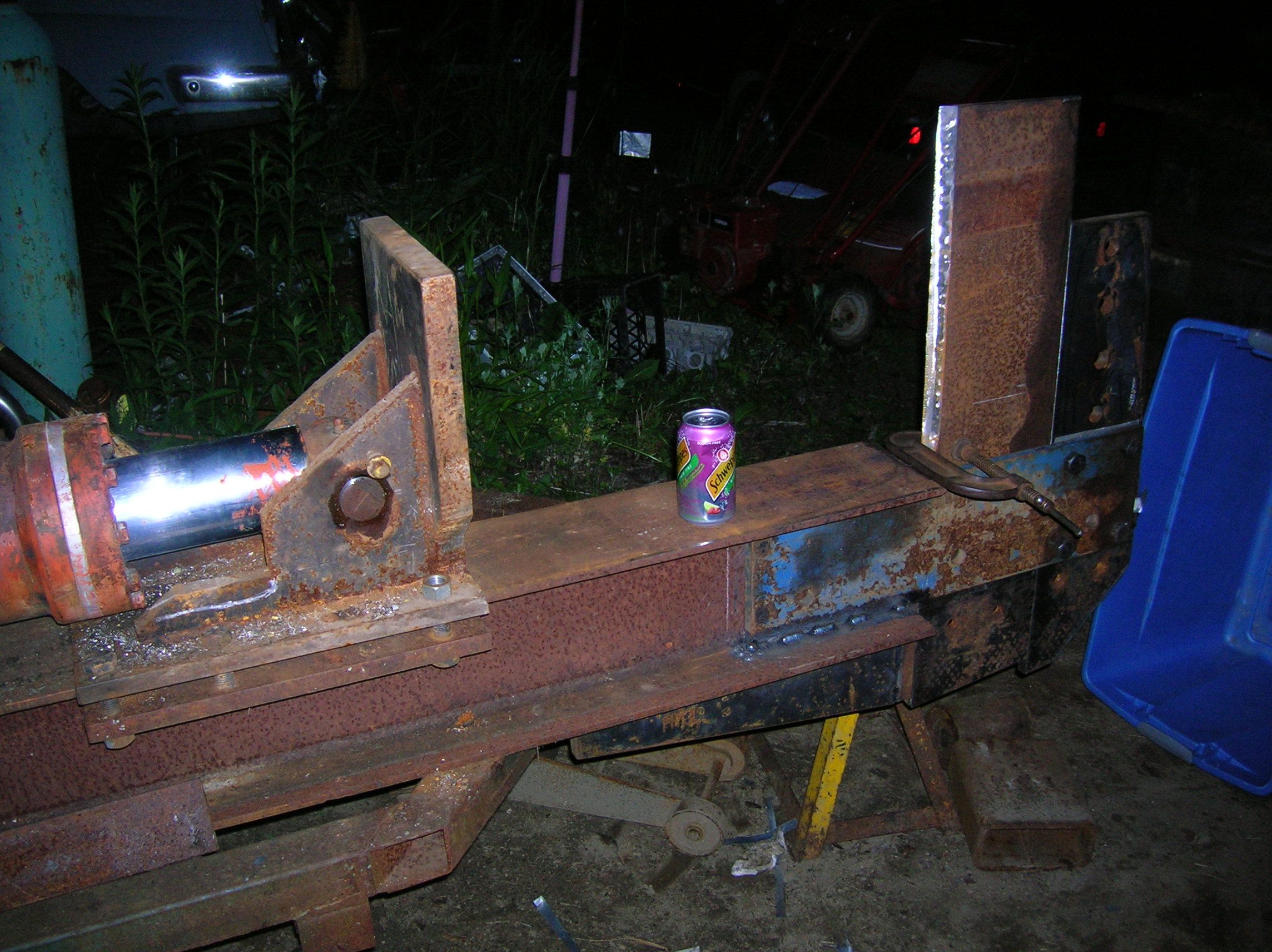
The start:
Chunk of I-beam from the scrapyard, section of pallet racking, and a pair of Saab 900 axles. The springs, hangers, and coupler were purchased new.
 From the look of the lawn, this is before I graded and rocked that section for better passage of the f350 loaded with firewood.
Powerplant. I have a few (ahem) Saabs on the premises, and so it seemed like a good use of a spare engine. Wasn’t sure how the whole mess would go together, so opted to mount the motor to it’s own subframe. As it turns out, the pump mounted to the right side was water damaged in a previous life, and of no use.
View from the other side.
 Lifting sling. Back then I had fewer means of hoisting large objects, so I set this up to lift with either the car lift or engine hoist.
 Mock up.
 And this how I left it.
 Begin the begin:
Fresh from the margins of the hayfield. Had to bomb a few hornets.

Cutting parts from plate. The Saab as background is consistent theme, though the color changes from time to time…
Working on the wedge backstop bracket.
Makes more sense from this perspective.
Where it fits in the larger scheme.

Wedge stock test fit. 
Looks more wedge-like. The angle was rough cut with the torch, then ground with the Metabo. That’s the last time I go that route. When I build the 4-way next summer, I will either make a fixture for the mill table, or buy an angled cutting bit so as to save a few hours and a tub of elbow grease.
Truing the back of the wedge plate on the Kearney and Trecker mill.

Like so. This should ensure that the pressure is evenly distributed against the backing plate.
Test fit. Made the wedge taller. This rig has to split anything over 13″.
More reinforcement. Those holes were already in the plate…
Hopefully the bracing will prevent the wedge from bending over backward.

Pulling it all together before welding the blue side plates to the beam.
End view. This thing is getting heavy.

Locating pin holes to set wedge height.
Detail.

With push plate and ram. The push plate and rail guides were built as part of the original project. The ram is from the Prentice loader. I had purchased a duplicate cylinder for the processor project way back when, and it was in better shape than this orange unit, so it went to the loader.
A big cylinder needs a big pump. Unless you have time to waste. I pulled the pump from the old Wain-Roy Hoe.It isn’t going to be digging holes anytime soon.
The Cessna pump was originally mounted to drive off the crank pulley, and so I’ll mount it alongside the motor rather than directly behind. This is actually an advantage, as I can gear it up or down to better match the flow requirements with the available horsepower and ideal throttle setting.
I had a dumb moment though, and welded the pump plate to the motor frame. It should be tied to the motor, which is isolated from the frame.
Duh. I’ll fix that shortly. Stay tuned.

Chain drive mock-up.
 Shaft support bracket.
 Drilled and tapped for pillow blocks.
Like so.
And here’s the remounted pump bracket.
Push plate clamp spacers. Rotabroach bits are pricey but so worth it.
 Ovalizing for adjustment.
Shimmed and clamped.
Truing up the ram anchor block side plates. Typically, I will weld mating parts together for boring and truing, then grind off the welds for assembly.


The ram is wider than the beam, so I made a sub-assembly which then bolts to the built-up flange.
Test fit.
Braced and welded. The junk steel in front is there to prevent warping and will be cut off after cooling. When all was said and done, the pin slid right out, and that was with only a few thousandths clearance on the bore.
Resealing the ram. The boom on the Prentice settled rapidly, which is why I swapped it for the good spare. This is what I found on disassembly. Both seals were torn. Some of this is from standard wear, but there was water in the fluid, and a line of rust in the bottom of the barrel that probably hastened the tearing. The two cup seals and packing were right around $150 from the local hydraulic rebuilder. I scraped and polished out the rust by hand with single edge razorblades, emery paper and Scotchbrite.
Not exactly aerospace grade work, but then this is just a splitter.

The piston is held in place with a very large nut. Large nuts, large torque, large wrench. (The slider handle was already bent. Really.)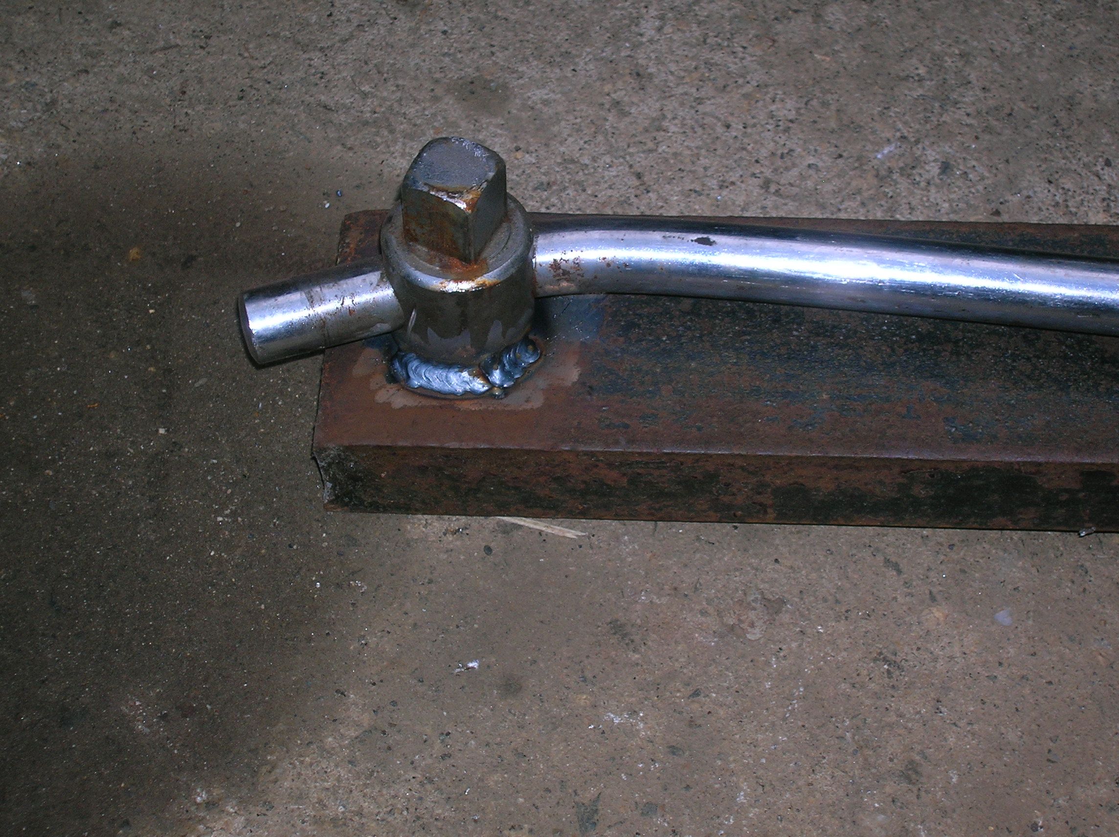
Seven feet ought to be enough of a multiplier?

Paging Archimedes…..Had to bounce on it a few times @185lbs.
With the ram in place, I can configure the hydraulic tank mounts. I have a reservoir from an idle machine that should work out ok.
Mock up.
Roughing in the pressure and return lines. The pump has a small second stage for the power steering on the backhoe. For the time being, that feed will go directly back to the tank.
Block guides.
 Locating prior to tacking.
 Probably a little light for the job, but fine for the first round of testing.
 With a 6″ bore and a 4″ rod, there is a fluid imbalance between the extend and retract. The rod side of the cylinder can fill faster than the piston side can empty, which bogs the engine and adds heat to the system.
The solution, as also used on the processor, is a dump valve. This valve is tripped by a pressure spike drawn from the rod end at the start of the retract cycle, at which point the fluid is routed from the piston end directly back to the tank, rather than back through the control valve. The valve then resets for the next extend cycle.
These tallied up to around $200 plus or minus. I had the large diameter hoses left over from a surplus purchase of hose.
 Part number.
 3/4 line is pressure to ram extend. 1/4 line is pilot (valve actuation signal) from rod end. 1″ line is return to tank.
 Side view.
 Hard mounting the valve to the cylinder was the most expedient route at the time.
 Pilot tap at rod end.
 Dump, valve, and pump auxiliary return.

Ready for the first round of testing. The opening is such that I should be able to drop two 16″ blocks into the splitter at the same time with the grapple bucket. At some point I will set up a remote valve control so I can actuate the splitter from the cab of the loader.

This is with the preliminary gearing. The local tractor supply had very few cogs available, and the order from Surplus Center hadn’t come in yet.
http://youtu.be/xxZPCDCZmK4
Update 6/11/15
The original plan was for a 4 way (rather than 2 way) wedge.
To that end:

Realized that if I tacked the main knife into a piece of channel, I’d get a decent edge.
Could have flipped the head on the Bridgeport, but the K&T has a powered feed, and I’m lazy.

There’s a lot of overhang on the work, so the cuts are light.

Hand ground edge and better view of the fixture.

“Ooh, shiny!” (Obligatory obscure pop culture reference).

Missed centering the edge by a few thousandths, but close enough.

With the center blade cleaned up, I can move on to the wings.
The stock already had a flame-cut bevel.

Again, light cuts on account of overhang. The problem here was the fixture warped a little from welding, and the base had to be trued to prevent movement on the mill table.

Single bevel prevents blocks from jamming between the wing and out-feed table.

Tacking up on the portable, adjustable welding table. The tail of the wings overhang to contact the blade stay. An attempt to reduce twisting.

Who knew Rubbermaid was into welding supplies?

Hip to be square. (The junk that gets stuck in memory…)
The wing base was trued on the mill, but you still want to be careful on tacking, and the initial welds to avoid pulling in either direction. One of the interesting things about welding is the way you can manipulate the materials as you go.

At max height. One of the next modifications will be a hydraulic lift for the knife assembly for easier adjustment.

Trailing edge of wings support the assembly.
This modification worked out very well. Previously, the two way split often found the large blocks falling off the table before the conveyor. With the four-way, they stay up. Hadn’t planned on that outcome, but it’s a nice bonus.
https://youtu.be/Snh1ObXheNc